Hi all,
I solved this issue with RTDE.
As far as l know, UR CB 3 (UR3) does not support Modbus RTU over RS485.
So, I just used a digital output of UR via RTDE.
A goal of this post is how to control the dynamixel from PC via UR3 (I do not need complex action or else).
Here is the solution.
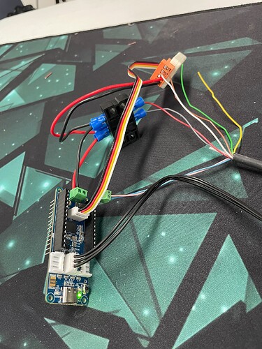
First, set wiring of UR3 and openRB-150 correctly.
Second, write a .ino code for openRB-150 and upload it via arduino-ide.
Third, write a python code to control the end effector via RTDE.
- Wiring
UR cable is a M8 8pin cable which has 8 color cables in it.
Each cable has its own signal domain.
We only consider ground, input voltage, tool output.
RED : ground
GRAY: 12/24V
BLUE: tool output 0
PINK: tool output 1
I connected each cable with openRB-150 as
RED : ground — Terminal VIN ground
GRAY: 12/24V — Terminal VIN +
BLUE: tool output 0 — PB10 (D4)
PINK: tool output 1 — PB11 (D5)
You can check the details of openRB-150 in here
Also, you should set UR3 output voltage to 12V in teach pendent.
- OpenRB-150 setting
As we set PB10 (D4) and PB11 (D5) as tool output 0 and tool output 1 each, we should match it in .ino code.
Here is the simple code example.
#include <Dynamixel2Arduino.h>

// DYNAMIXEL define
#define DXL_ID 1
#define DXL_PROTOCOL_VERSION 2.0
#define BAUDRATE 2000000
#define DXL_SERIAL Serial1
#define DEBUG_SERIAL Serial
const int DXL_DIR_PIN = -1;

// Digital Input Pins
#define INPUT_PIN_OPEN 4  // PB10 (D4) for 'Open Gripper' command
#define INPUT_PIN_CLOSE 5 // PB11 (D5)

// Variables
uint16_t minimum_pos = 0; // example value
uint16_t maximum_pos = 1000;

Dynamixel2Arduino dxl(DXL_SERIAL, DXL_DIR_PIN);

void openGripper() {
    dxl.setGoalPosition(DXL_ID, minimum_pos);
    DEBUG_SERIAL.println("Gripper opening...");
}

void closeGripper() {
    dxl.setGoalPosition(DXL_ID, maximum_pos);
    DEBUG_SERIAL.println("Gripper closing...");

// Setup
void setup() {
    DEBUG_SERIAL.begin(115200);

    // Initialize DYNAMIXEL
    dxl.begin(BAUDRATE);
    dxl.setPortProtocolVersion(DXL_PROTOCOL_VERSION);

    if (dxl.ping(DXL_ID)) {
        DEBUG_SERIAL.println("DYNAMIXEL is connected");
    } else {
        DEBUG_SERIAL.println("Failed to connect to DYNAMIXEL");
    }

    // Set DYNAMIXEL operating mode
    dxl.torqueOff(DXL_ID);
    dxl.setOperatingMode(DXL_ID, OP_POSITION);
    dxl.torqueOn(DXL_ID);

    // Initialize Digital Input Pins
    pinMode(INPUT_PIN_OPEN, INPUT_PULLUP);  //
    pinMode(INPUT_PIN_CLOSE, INPUT_PULLUP); //

    DEBUG_SERIAL.println("Setup complete");
}
}

void loop() {
    // Read the digital input pins
    bool open_signal = digitalRead(INPUT_PIN_OPEN);
    bool close_signal = digitalRead(INPUT_PIN_CLOSE);

    // Check for Open Gripper command
    if (open_signal == LOW && close_signal == HIGH) {
        openGripper();
    }
    // Check for Close Gripper command
    else if (open_signal == HIGH && close_signal == LOW) {
        closeGripper();
    }
    // No command or both commands received
    else {
        // Optional: Handle idle state or invalid command state
    }

    delay(100);
}
- Python code from PC
Install rtde library using pip.
Then you can control the end effector using rtde IO interface function.
Here is a simple code example.
from ur_rtde import RTDEIOInterface
import time

ur_ip = "your_ur_ip"


rtde_io = RTDEIOInterface(ur_ip)


def open_gripper():
    rtde_io.setToolDigitalOut(0, True)   # Tool DO0 HIGH
    rtde_io.setToolDigitalOut(1, False)  # Tool DO1 LOW

def close_gripper():
    rtde_io.setToolDigitalOut(0, False)  # Tool DO0 LOW
    rtde_io.setToolDigitalOut(1, True)   # Tool DO1 HIGH

if __name__ == "__main__":
    # Open the gripper
    open_gripper()
    time.sleep(2)

    # Close the gripper
    close_gripper()
    time.sleep(2)
I hope this post helps.
Best regard,
Soochul
