In our company, we want to use a Cobot for a special application : glue application in the corners of a circular face ( alike this video https://www.youtube.com/watch?v=jWhsL74CL9c)
I want the robot to add an angle α at its movements in order to reach the corners all over the circular path like this :
In order to have the angle all over the path (at each points of the circular path) I changed the program : I added +/-0.4 radian at RX or RY for p1, p2, p3 and p4
Example : p1:=pose_add(center,p[ r ,0,0, 0.4 ,0,0])
Below the two programs that allow to have a circular path with an angle 0.4 :
It seems like for the first circle arc, the UR3 keeps an angle of 0.4 rad and then loose it when the second circle arc start… (the Robot is doing a wavy path all around the circle)
Like if the mid point of the arc is not controlled for angle (Rx,RY,RZ), only xyz position.
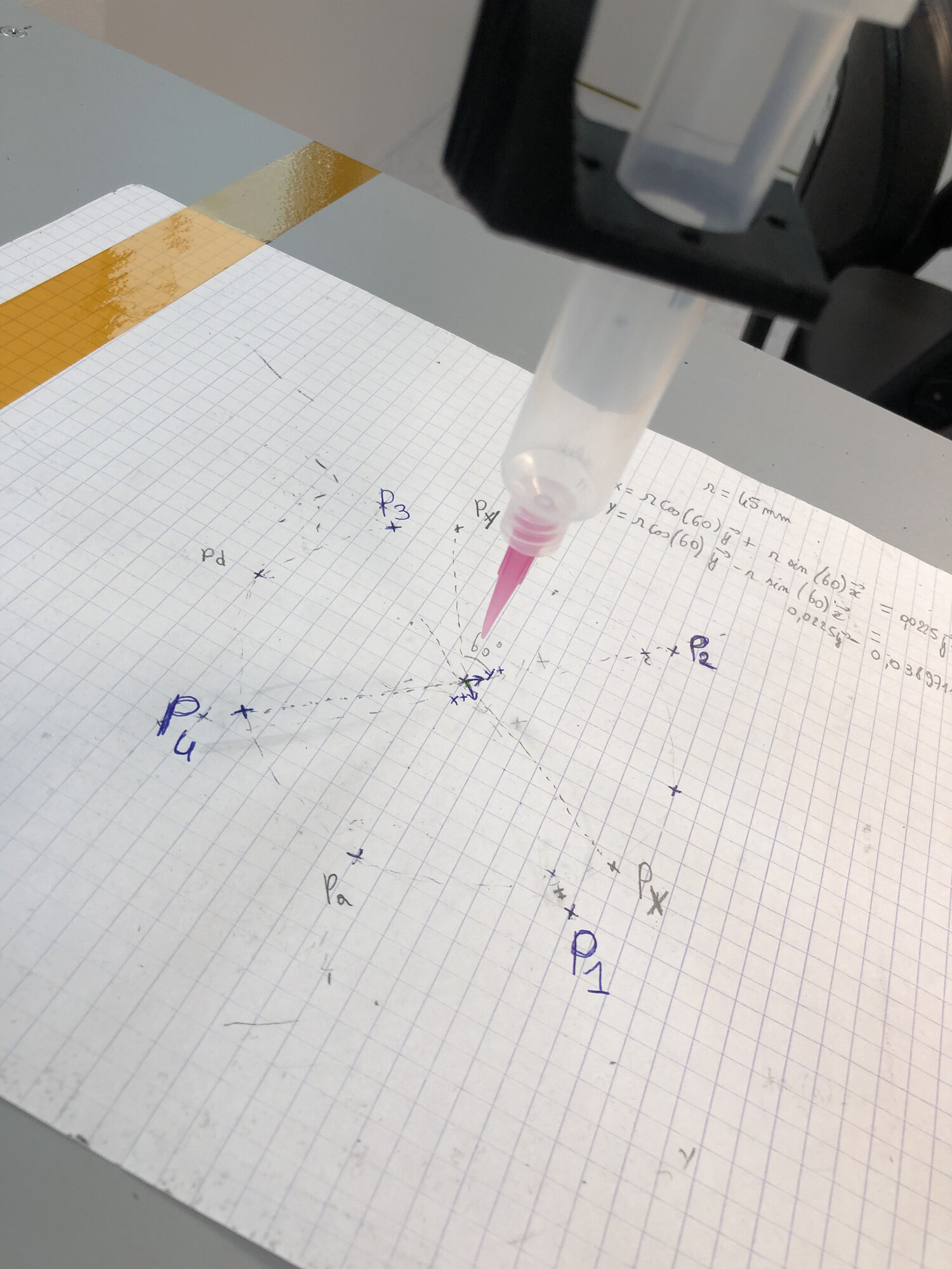
Does someone have a formula that calculate each positions around the circle and then using simply a movej to go to each of those points ?
That video was not performed using the built-in circle move. We actually defined the point that it was going to and moved the point around the perimeter of the circle and then had the robot move to that point. We controlled the speed by changing the step size of the radians between rotations.
With this solution we built in the angle that we wanted to hold the dispenser into the tooling, not the TCP. The TCP position was straight out the tool flange at the center of the flange.
So the process is move to the center point and then move out to the start of the circle and then basically spin the center point and move to it. We used the radiusAdjustment to compensate for the circle being larger than the tool. This was a very quick and dirty solution but it worked, we ran over 10k parts using this algorithm and its simple to implement
This is a number of years old but here is that section of the robot program
hbCircleMove
         Parameters
           Set loctiteMach=On
           rz≔-.785. #Starting point of the circle
           z≔5/1000
           circleOffset≔3.5 #This is 3.5mm from the center point to compensate for the tool was slightly smaller than the lid
           y≔circleOffset/1000
           x≔0
           radiusAdjustmen≔circleOffset*2/180/1000
         MoveJ
           siliconeCent_var (This is the center point of the circle)
         MoveJ
           point≔p[0,y,z,0,0,rz]
           pointTrans≔pose_trans(siliconeCent_var,point)
           pointTrans
         circle move
           Movement
             Set dispenseSilicon=On
             Loop 360 times
               rz≔rz+.0175
               MoveJ
                 var_3≔Loop_1
                 If Loop_1<180
                   y≔y-radiusAdjustmen
                 ElseIf Loop_1>180
                   y≔y+radiusAdjustmen
                 If Loop_1<90
                   x≔x-radiusAdjustmen
                 ElseIf Loop_1>90 and Loop_1<180
                   x≔x+radiusAdjustmen
                 ElseIf Loop_1>180 and Loop_1<270
                   x≔x+radiusAdjustmen
                 ElseIf Loop_1>270
                   x≔x-radiusAdjustmen
                 point≔p[x,y,z,0,0,rz]
                 pointTrans≔pose_trans(siliconeCent,point)
                 pointTrans
             Set dispenseSilicon=Off
             Wait: 0.5
             MoveJ
               clearCup
             Set loctiteMach=Off