Rotate With Respect to a Feature

I feel dumb asking this because it seems like it should be so simple. What URScript gets your rotation about a Feature? I want the exact same functionality as if I chose my Feature from the dropdown, and held +X on the Move Screen. None of the Pose Trans attempts I’ve tried so far seem to be working correctly. The examples I’ve seen from UR don’t work right either if the Feature has a different orientation than Base. In my example, My Feature is (more or less) rotated 90 degrees from Base such that +Z of my Feature lines up with +X of Base.

If I put a cartesional shift in, and use Pose_trans(), I get what I expect:

myPose = p[0.5, 0, 0, 0.5, 0, 0]
myVar = pose_trans(Plane_1, myPose)

myVar then comes out as p[0,0,0.5,0.5,0,0]. It has correctly translated that 500mm in my Plane_1 X is actually 500mm in Base Z. But it does NOT translate my 0.5rad rotation in Plane_1 RX as a rotation in RZ of Base. It just continues to say that’s 0.5 rad in RX. What gives?

Hi Its not a dumb questions at all.
this (Rotations in 3D) is always way more confusing then it feels like it should be.

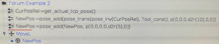
So the way I solved this was

  1. converting the current pose of the arm into the feature coordinate system
  2. applying the offset
  3. converting back to the base coordinate system

(I do think there is an easier way to do this with the new Motion Plus System)

so my notation

B1 = “orginal base”
P1 = “current pose in orginal base coordinates”
B2 = " feature base"
P2 = "current pose in feature coordinates!

assuming that the two combinations of bases and poses, points to the same place in space, in some world coordinate with origin in p[0, 0, 0, 0, 0, 0], and that B1 and B2 are offset from this world coordinate. we can setup the matrix equation

B2 * P2 = B1 * P1

we can now isolate P2

P2 = inv(B2) * B1 * P1

as B1 is [0, 0, 0, 0, 0, 0] it can simply be removed
(for the math nerds its equivalent to the identity matrix " B1 = I ")

P2 = inv(B2) * P1

this gives us the URScript code as

pi = 3.1415926535897932384626433
feature_frame = p[0., 0., 0., 0., 0., pi/2.]
current_pose_in_base_frame =  p[0.5, 0., 0., 0., 0., 0.]

pose_in_feature_frame = pose_trans(pose_inv(feature_frame), current_pose_in_base_frame)

as we now have the pose in the frame coordinate system we can add the offset we wish.

feature_offset = p[0.5, 0., 0., 0., 0., 0.]
pose_in_feature_frame_offset = pose_trans(feature_offset, pose_in_feature_frame)

now we need to revert back to our original coordinate system of the base by isolating for P1 instead of P2.

B2 * P2 = B1 * P1
P1 = inv(B1) * B2 * P2
P1 = B2 * P2

again as B1 is the pose version of nothing we can simply ignore it

pose_offset_in_base = pose_trans(feature_frame, pose_in_feature_frame_offset)

in total this results in the code

pi = 3.1415926535897932384626433
feature_frame = p[0., 0., 0., 0., 0., pi/2.]
current_pose_in_base_frame =  p[0.5, 0., 0., 0., 0., 0.]
feature_offset = p[0.5, 0., 0., 0., 0., 0.]

pose_in_feature_frame = pose_trans(pose_inv(feature_frame), current_pose_in_base_frame)
pose_in_feature_frame_offset = pose_trans(feature_offset, pose_in_feature_frame)
pose_offset_in_base = pose_trans(feature_frame,  pose_in_feature_frame_offset)
1 Like

Thanks for the detailed, well-explained breakdown here. I’m probably missing the pose_inv() calls, since I really didn’t know what that was doing. I will try to get this program to a stopping point and try this out and see if it works!

So I went ahead and gave this a try and unfortunately it does not do what I expected it to. The offset I passed it was p[0,0,0,d2r(10), d2r(5), 0]. I wanted it to take the position and rotate the TCP 10 degrees in myFeature’s X, and 5 degrees in myFeature’s Y. Exactly how it would do so if I had selected myFeature from the dropdown box in the Move Screen and held the direction arrows.

The code you provided doesn’t do this. It looks like it’s rotating around SOMETHING, but the TCP moves as well. Maybe it’s rotating at the tool flange and I need to add something to account for the TCP (it’s a welding torch), I’m not sure.

Hi.

In this type of cases you should apply each rotation one at a time, instead of both at ones.
As the combined rotation is not equal to rotating each axis alone.

If this still do not work please do post your whole script calculation.

As I do not think I can help you otherwise.

Kind regards CG1

I wasn’t completely sure how to add them independently, so here’s what I tried. It did something else than it did before, but was even more wrong than before:

myOffset1≔p[0,0,0,d2r(10),0,0]
myOffset2≔p[0,0,0,0,d2r(5),0]
poseInFF≔pose_trans(pose_inv(Plane_1), myPoint)
poseInFFOffset≔pose_trans(myOffset1, poseInFF)
poseInFFOffset≔pose_trans(myOffset2, poseInFFOffset)
poseOffsetInBas≔pose_trans(Plane_1, poseInFFOffset)
MoveL
  poseOffsetInBas

At the end of the day, all I’m really trying to do is emulate what you can do easily on the Move Screen. Select a Feature, click the “Tool Positions” Boxes in the top right, type 10 degrees in RX and 5 degrees in RY and move the robot where it wants to go. That’s it.

Appreciate the help cg1

This code will rotate the robot around the tool RX axis and RY axis 45 degrees respectively:

Just like on the move tab. At least when I’m using it. :slight_smile:

Rats! I thought I was actually going to be able to help one of you guys but of course you beat me to it. People be sleeping on those pose_adds…

I don’t want to rotate around Tool though. I want the TCP to rotate the same way it does when you select a FEATURE from the dropdown box and THEN hold the Move arrows

If you’ve got an answer I’m all ears. Nothing anyone has suggested yet (including multiple folks from UR) have gotten me what I’m looking for.

@efn here’s what happens when I run your code:
example

As you can see the TCP (tip of the weld wire) does NOT rotate in place. I have no idea what the robot is trying to do, but I had to stop it before it crashed into itself.

And here’s the code that produced this result:

Right. I misunderstood you. Can you try out this code? :slight_smile:

MoveL is with Point_1 as Feature.

But I completely agree. That is much more difficult to figure out, than it should be.

1 Like

I’ll try that code, but it looks like you’re only providing rotation in 1 axis. I need rotation in both the X and Y, and multiple people say you can’t do that in the same command (though I don’t understand why you can’t use rpy2rotvec() to achieve that but whatever). So how should I write it such that I can do 10 degrees in Plane_1’s RX and 5 degrees in Plane_1’s RY?

Do two pose_add sequentially with two separate PoseOffsets.
I have never tried the rpy2rotvec(), but I guess it should do this, too, yeah.

@efn You got venmo or cash app? I don’t think I can thank you enough for your solution here. I spent DAYS worth of time trying to crack this and gave up.

I created a case with myUR. I was in talks directly with some of the UR devs. I tried a ton of stuff myself. Nothin.

Here’s what finally worked. I know it’s a little different than what you posted, but that’s because what I REALLY wanted was not necessarily to ADD rotation about a Feature, but just FIX a position to a particular rotation about a feature. I didn’t know how to express that but figured if someone could just show me how to rotate about a Feature at all I could figure out that specific problem. And this worked beautifully. This disregards the orientation of the taught point and just forces the rotation values on top of this.

I still don’t know that I’d call this SIMPLE, but at least it’s only 3 lines instead of like 10. Going to make this into a function now so I never have to go through this again.

Haha, that’s no problem. I’ve been spending so much time myself on working with features. I hope UR makes some built-in functions at some point that makes it easier. :slight_smile:

I’ll be using the rpy2rotvec() in the future, as well! Never thought of trying it out.