Hello,
I have a project, which uses an Igus linear rail package. The package includes their D1 stepper driver https://www.igus.com/product/D1
The Stepper driver can use these communication methods.
Digital inputs/outputs
Analogue inputs
CANopen
ModbusTCP
I have been in contact with Igus technical staff and there are 3 option
- Binary Mode
- Tip/Teach Mode
- Modbus
Option 1 seems to be the best option for the simple movements needed on for this project. I have little experince with modbus and the Tip/Teach does not provide enough positions.
Base on conversation with Igus technical staff
These bits can be called upon for going to specific lines on the binary profile, and there is up to 32 positions which can be call upon. You just need to leave the ‘next’ column blank and it wont go to the next position until you signal for it with the proper binary representation in bits.
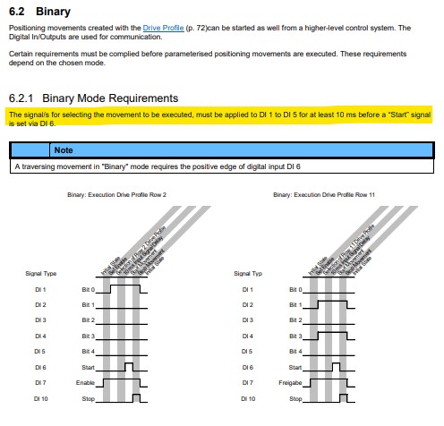
What I am trying to do is use their “Binary mode” which turns on a series of Digital inputs (bits), to move the motor to a defined positions, set up within the driver via it’s interface.
I can use the UR to turn the inputs on and off, which does move the motor to the position for the corresponding on/off bits.
My questions can I set up a thread or something else within the UR robot code that will have all of the on/off inputs bits set to the corresponding movements and call a specific move from the program in the UR that will call a specific sequence and move to desired positions?
For example. I have a sensor when HI, calls for the rail to move to POS1. In that subroutine DI5, DI4 DI3 DI2 and DI1 are set to LOW, moving the linear rail to home. Then when sensor is LOW, calls for the rail to move to POS2, but now in that subroutine or another DI5, DI4 DI3 DI2 are set to LOW and DI1 is set to HI.
I have added the tables from the manual to try give a better understanding
This is my first time posting so I hope this is in the right location and makes sense. Any help on how to achieve this would be greatly apricated.
Thank You.


