Hello everyone,
our company has purchased a used UR10 from a machine dealer. My colleagues and I are supposed to set up a test track. But first, we need to make the robot operational.
Our problems are as follows:
-
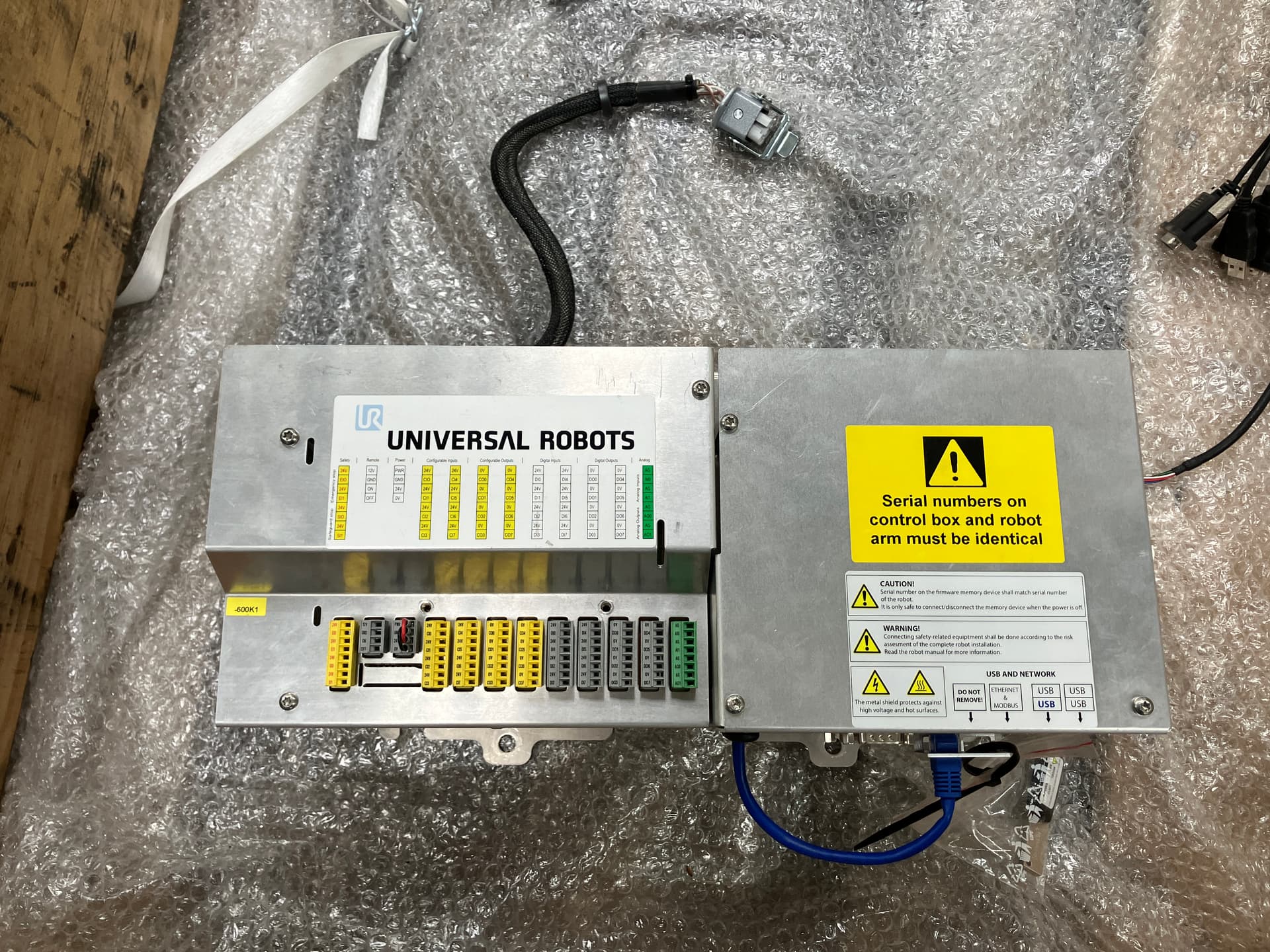
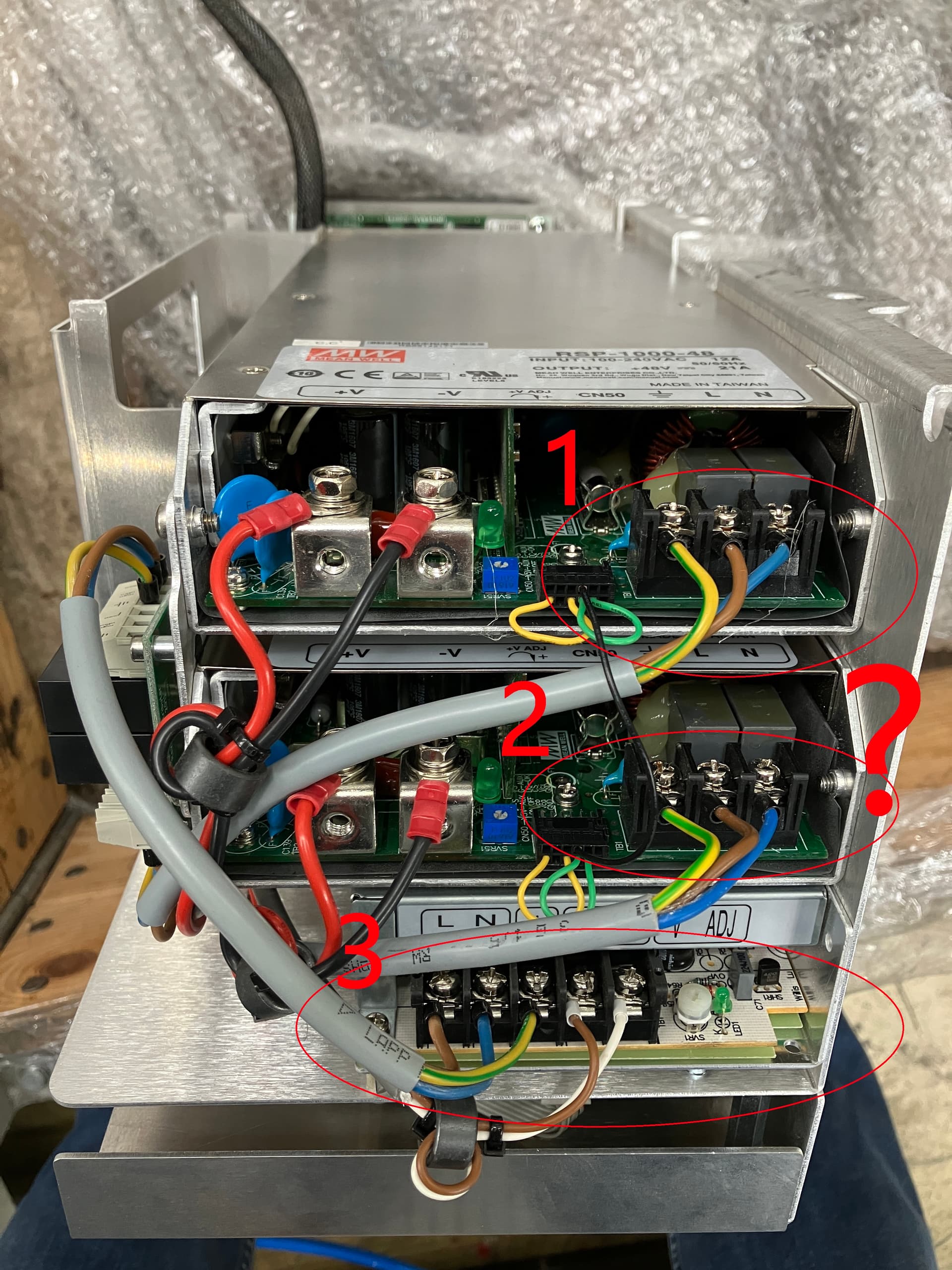
Unfortunately, the robot only comes with the controller. A control cabinet is missing. The power supply that leads to the controller is also missing. There should be a power line with a socket/IEC connector. Our electrician is willing to create something himself, but he is unsure where exactly to connect the wires. Perhaps you could provide some advice. I have taken photos to illustrate the situation better.
-
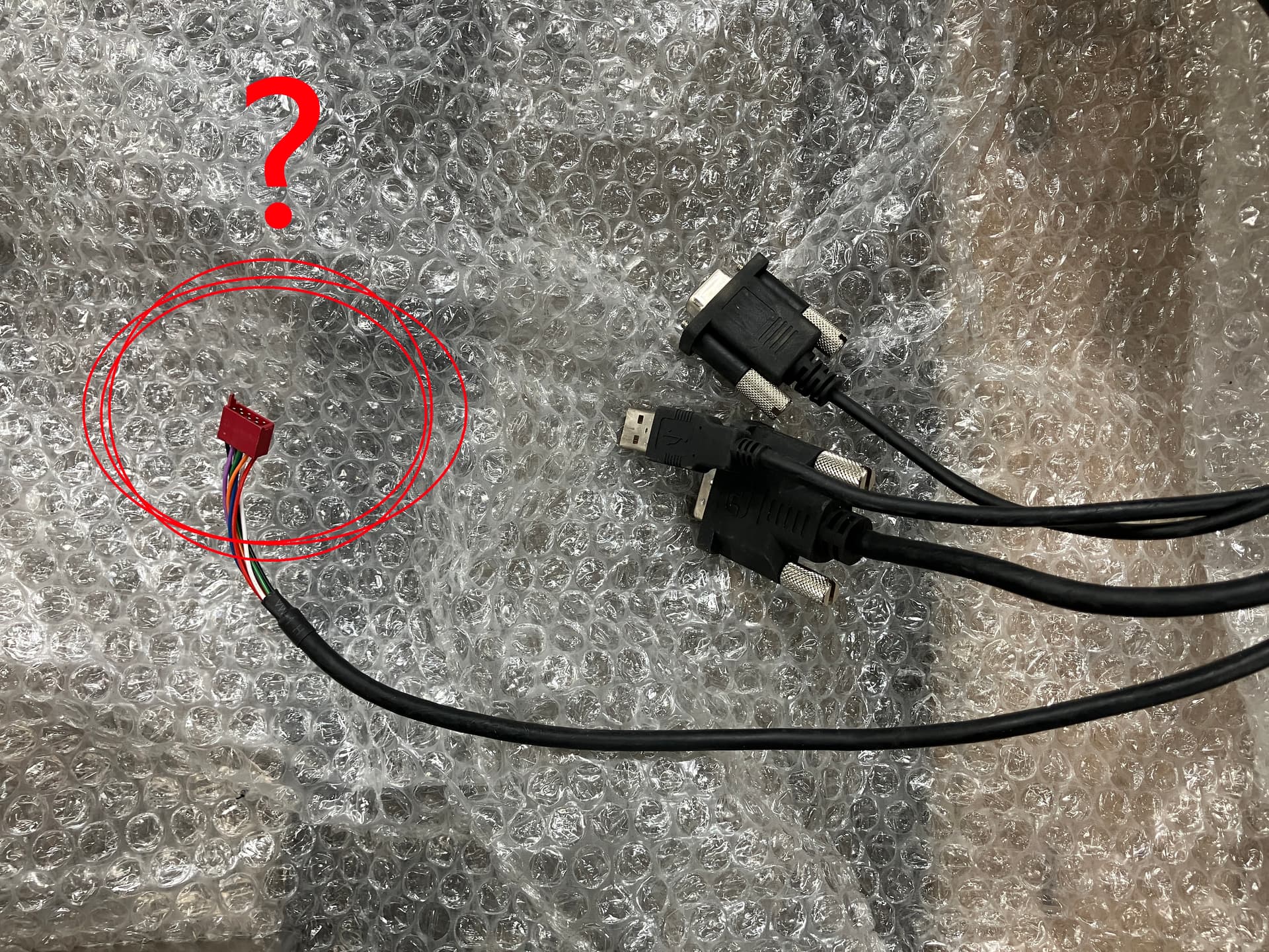
There is a red connector on the cable of the panel - see the picture. Where does this plug in?