Relay Arduino Push-Button UR10e // debugging

Hello everyone,

I have setup a relay-module and a Arduino with a Push-Button (Kurzhubtaster as we say in Germany) to trigger the Digital Input. I think I have kabelt up everthing right… but it’s not working.
The “wait“ function is not triggered when I push the button (I tried Hi & LO and just wait for 2 sec what worked).
So I did something wrong but can’t find my mistake…
I tried to document my setup with the pictures below.
Maybe somebody can help to debug the setup.

You can confirm that the IO on the robot controller is changing state as you expect from your Arduino? If so, there’s really nothing left to troubleshoot. The way your screenshot shows, you would have to keep the IO ON for the robot to wait. Keep in mind, the robot will execute all 8 waypoints after that, regardless of the state of the pushbutton. It’s not continuously being checked, if that’s what you’re trying to achieve.

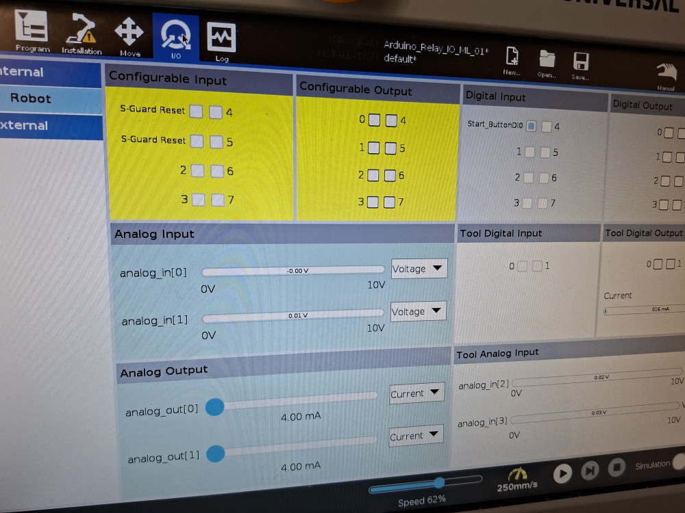
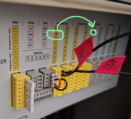
I can’t see the change by the input on the pendant, maybe I don’t know the right place to observe it.
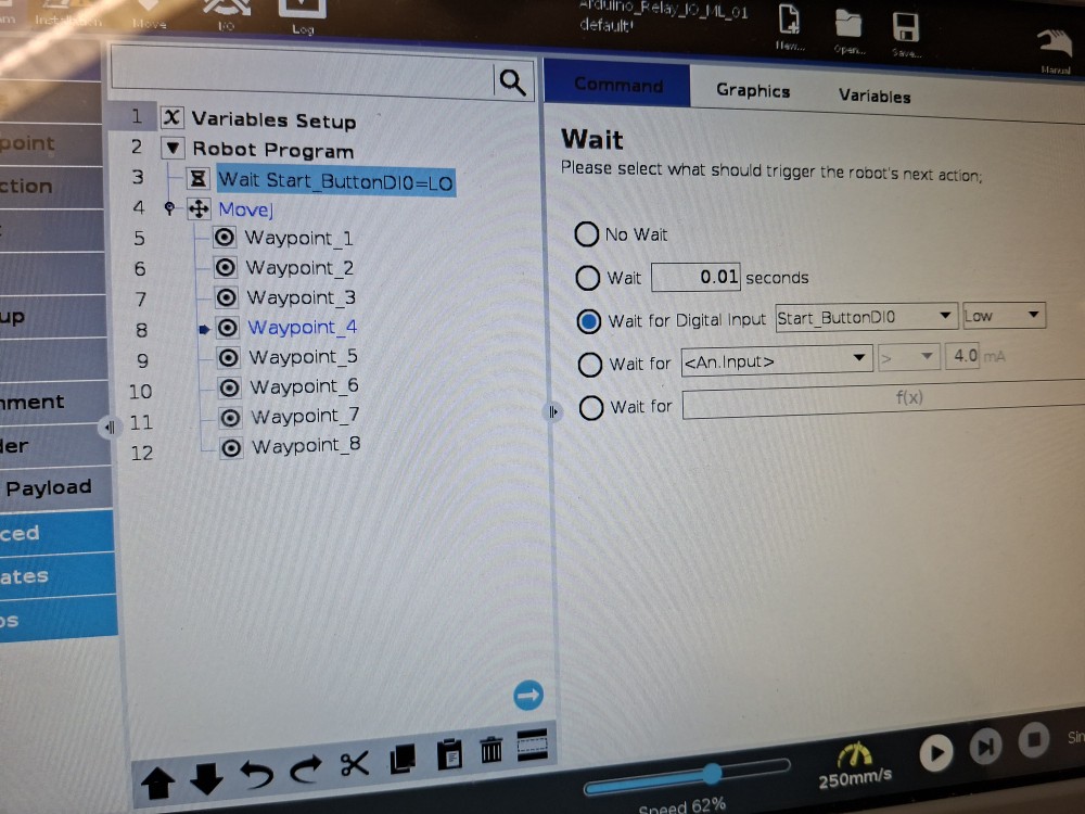
The Program on the Teach-Pendant is just starting when I pressed “play“.
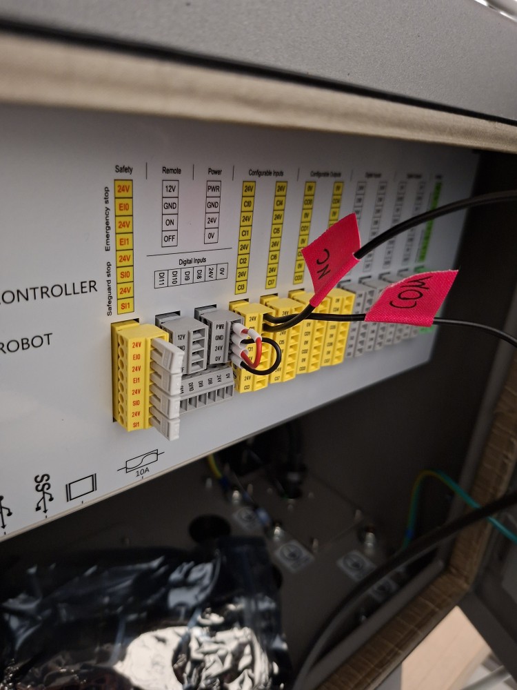
I now switched NC to NO and it’s not starting anymore.
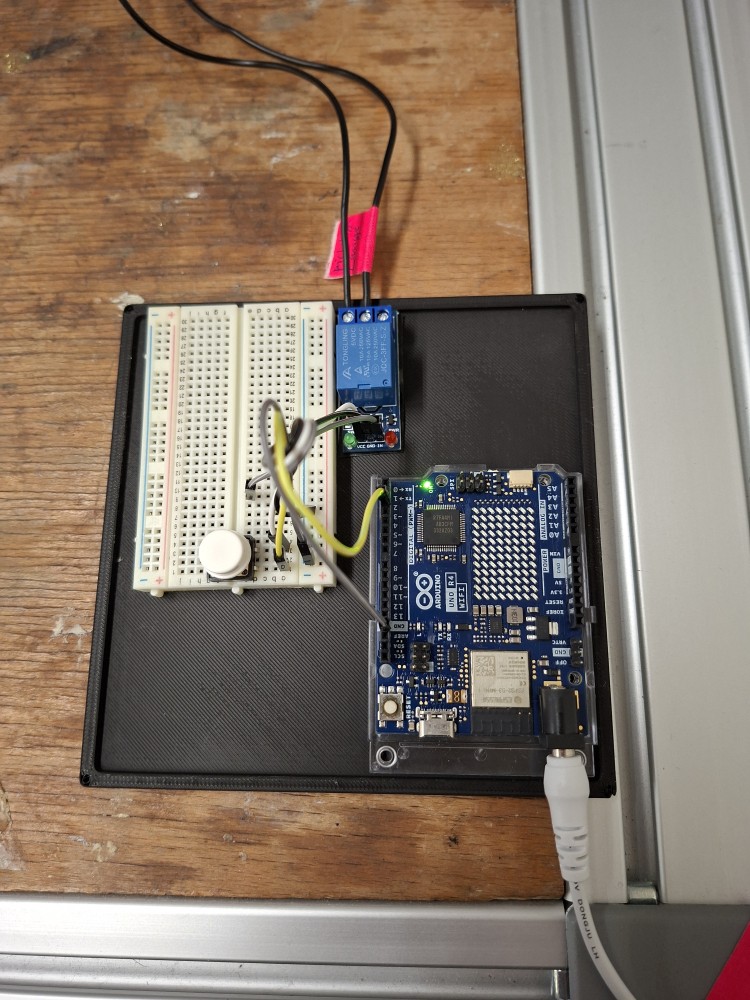
It’s like the relay is not changing its state right. But the PWR LED (and Arduino LED) is lighting up when I press the button.

I can’t upload the Video…

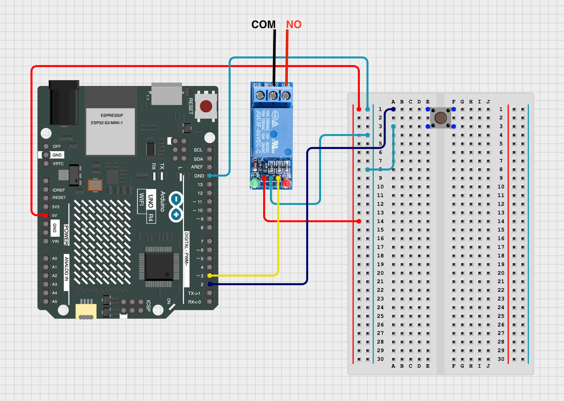
But here is my Arduino Code.

// 05-12-2025

// Kurzhubtaster (Push-Button) mit Debouncing und Toggle-Funktion

const int buttonPin = 2; // Push-Button (gegen GND)

// Debounce-Variablen

unsigned long lastDebounceTime = 0;

const unsigned long debounceDelay = 50;

bool lastButtonReading = HIGH; // letzter roher Tasterwert

bool buttonState = HIGH; // entprellter Tasterwert

bool toggleState = false; // EIN/AUS-Zustand

void setup() {

Serial.begin(9600);

pinMode(buttonPin, INPUT_PULLUP);

}

void loop() {

// --------------------------

// BUTTON DEBOUNCE

// --------------------------

bool reading = digitalRead(buttonPin);

// Zustand hat sich geändert → Entprell-Zeit starten

if (reading != lastButtonReading) {

lastDebounceTime = millis();

}

// Wenn der Zustand stabil ist …

if ((millis() - lastDebounceTime) > debounceDelay) {

// … und sich der entprellte Zustand ändert …

if (reading != buttonState) {

  buttonState = reading;


  // BUTTON wurde gedrückt (LOW) → Toggle umschalten

if (buttonState == LOW) {

    toggleState = !toggleState;

if (toggleState) {

Serial.println(“Toggle = EIN”);

} else {

Serial.println(“Toggle = AUS”);

}

}

}

}

lastButtonReading = reading;

// (Hier kann eine Aktion ausgeführt werden,

// abhängig von toggleState)

}

OK let’s backup then. Take the debugging one step at a time, rather than looking at the end result (robot program working or not). Let’s isolate just the Arduino. Connect it to your computer and run its terminal and push the button. Have something print to the console on click and release. Verify that the button is triggering code when you think it should be

Now monitor the output of the arduino. Again, this can be just printing the voltage level to ensure that it’s working as you expect.

Now take a multimeter and probe the contacts of your relay. With the meter set to continuity (beeps when a short is detected), probe across the normally closed contacts. You should hear it beep. Now probe the Normally Opened contacts. You should NOT hear a beep. Now make your Arduino fire its output and probe again. The NC contact should no longer beep, and the NO contact should be beeping.

At this stage you’ve verified the Arduino and the relay.

Now just monitor the IO tab of the teach pendent and see if your robot into is following state of the relay. If it is, you should be good to go.

Hello,

You connected your “NC” wire to CI0 instead of DI0.

As shown in your first screenshot, CI0 and CI1 correspond to “S-Guard Reset”.

Try this:

image

Kind regards

1 Like

Thank you,

I already had that error and changed that, forgot to change the picture :sweat_smile:

Its now NC(Digital Input 24V) and COM(Digital Input DI0)

No problem.
Is the cobot’s 0V connected to the relay’s 0V and the Arduino’s 0V?

I don’t believe your relay and button are wired correct. Relay VCC must go to V+/5V/3.3V, GND to 0V and IN must be the 3.3V/5V signal from the Arduino.

Your Arduino output is what’s triggering the relay on the IN pin.

The button must have 5V/3.3V on one side of the contact and go to an input on the Arduino on the other (looks like it’s connected to the relay VCC?).

I solved it. I did not understand the Relay-Module and the Code right.

Now I changed the Code and the Arduino wiring…

// 10-12-2025

// Kurzhubtaster (Push-Button) mit Debouncing und Toggle-Funktion


const int buttonPin = 2;               // Push-Button (gegen GND)

const int relayPin = 6;               // Relay-Module IN to Pin 6 NOTE: Relay VCC to Arduino 5V Pin


// Debounce-Variablen

unsigned long lastDebounceTime = 0;

const unsigned long debounceDelay = 30;


bool lastButtonReading = HIGH;         // letzter roher Tasterwert

bool buttonState = HIGH;               // entprellter Tasterwert


bool toggleState = false;              // EIN/AUS-Zustand


void setup() {

Serial.begin(9600);

pinMode(buttonPin, INPUT_PULLUP);

pinMode(relayPin, OUTPUT);


  toggleState = false;

digitalWrite(relayPin, LOW); // Relais AUS

}


void loop() {


  // --------------------------

  //       BUTTON DEBOUNCE

  // --------------------------

bool reading = digitalRead(buttonPin);


  // Zustand hat sich geändert → Entprell-Zeit starten

if (reading != lastButtonReading) {

    lastDebounceTime = millis();

}


  // Wenn der Zustand stabil ist …

if ((millis() - lastDebounceTime) > debounceDelay) {


    // … und sich der entprellte Zustand ändert …

if (reading != buttonState) {

      buttonState = reading;


      // BUTTON wurde gedrückt (LOW) → Toggle umschalten

if (buttonState == LOW) {

        toggleState = !toggleState;


if (toggleState) {

Serial.println("Toggle = EIN");

digitalWrite(relayPin, HIGH);              // Digital Pin 6 EIN

} else {

Serial.println("Toggle = AUS");

digitalWrite(relayPin, LOW);              // Digital Pin 6 AUS

}

}

}

}


  lastButtonReading = reading;


  // (Hier könntest du später eine Aktion ausführen,

  //  abhängig von toggleState)

}
2 Likes

Now I’ve tidied up the wiring and the code:

// 12-12-2025
// Push-Button Debounced and Toggle-Function to trigger Relay-Module

const int buttonPin = 2;               // Push-button (to GND)
const int relayPin = 3;               // Relay module IN to pin 3 NOTE: Relay VCC to Arduino 5V pin

// Debounce variables
unsigned long lastDebounceTime = 0;
const unsigned long debounceDelay = 30;

bool lastButtonReading = HIGH;         // last raw button reading
bool buttonState = HIGH;               // debounced button state

bool toggleState = false;              // ON/OFF state

void setup() {
Serial.begin(9600);
pinMode(buttonPin, INPUT_PULLUP);
pinMode(relayPin, OUTPUT);

toggleState = false;
digitalWrite(relayPin, LOW); // Relay OFF
}

void loop() {

// --------------------------
//       BUTTON DEBOUNCE
// --------------------------
bool reading = digitalRead(buttonPin);

// State changed → start debounce timer
if (reading != lastButtonReading) {
lastDebounceTime = millis();
}

// If the state is stable …
if ((millis() - lastDebounceTime) > debounceDelay) 

{
// … and the debounced state changes …
if (reading != buttonState) {
  buttonState = reading;

  // BUTTON was pressed (LOW) → toggle state
  if (buttonState == LOW) {
    toggleState = !toggleState;

    if (toggleState) {
      Serial.println("Toggle = ON");
      digitalWrite(relayPin, HIGH);              // Digital Pin 3 ON
    } else {
      Serial.println("Toggle = OFF");
      digitalWrite(relayPin, LOW);              // Digital Pin 3 OFF
    }
  }
}

}

lastButtonReading = reading;

// (Here you could later perform an action
//  depending on toggleState)
}

1 Like

Just fyi: The wiring of your relay is still not correct according to your drawing. :slight_smile:
VCC must go to a constant 5V supply (as your IN is now). And IN is the receiving signal from your Arduino.

That being said, your solution will work since you will just be powering the relay with your signal output from the Arduino. Had your relay been self-holding for example, you would have had issues.

This should be right. :sweat_smile:

// 12-12-2025
// Push-Button Debounced and Toggle-Function to trigger Relay-Module

const int buttonPin = 2;               // Push-button (to GND)
const int relayPin = 3;               // Relay module IN to pin 3 NOTE: Relay VCC to Arduino 5V pin

// Debounce variables
unsigned long lastDebounceTime = 0;
const unsigned long debounceDelay = 30;

bool lastButtonReading = HIGH;         // last raw button reading
bool buttonState = HIGH;               // debounced button state

bool toggleState = false;              // ON/OFF state

void setup() {
Serial.begin(9600);
pinMode(buttonPin, INPUT_PULLUP);
pinMode(relayPin, OUTPUT);

toggleState = false;
digitalWrite(relayPin, LOW); // Relay OFF
}

void loop() {

// --------------------------
//       BUTTON DEBOUNCE
// --------------------------
bool reading = digitalRead(buttonPin);

// State changed → start debounce timer
if (reading != lastButtonReading) {
lastDebounceTime = millis();
}

// If the state is stable …
if ((millis() - lastDebounceTime) > debounceDelay)

{
// … and the debounced state changes …
if (reading != buttonState) {
buttonState = reading;

// BUTTON was pressed (LOW) → toggle state
if (buttonState == LOW) {
toggleState = !toggleState;

if (toggleState) {
  Serial.println("Toggle = ON");
  digitalWrite(relayPin, HIGH);              // Digital Pin 3 ON
} else {
  Serial.println("Toggle = OFF");
  digitalWrite(relayPin, LOW);              // Digital Pin 3 OFF
}

}
}

}

lastButtonReading = reading;

// (Here you could later perform an action
//  depending on toggleState)
}