For some pose, the rotation vector between the teach pendant and serial output of the robot is 180 out of phase. Is there any way to workarround?

I believe that the two poses are at exactly the same point, but there may be multiple solutions for the rotations, that fulfill this position.
the rotation axis is almost the same, one (0,0.713680855,-0.700471011), another is (0,-0.713775653,0.700374412). While the rotation angle is a bit large, i.e. 3.149166725 against 3.13403797 in rad (>0.5 degrees).
@chlai I am seeing the same thing for this point. I am using the RTDE to get back the actual joint positions as well as the TCP actual position.

So to confirm that there are two solutions I went in and switched the polarity of the RX, RY and RZ manually and as soon as I press OK the values change back to what they were before I changed them. So I ran another test and wrote a program that just assigns the current tool pose to a variable and the result of that was:
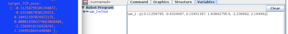
which matches what the RTDE is saying but if I check the move screen I am still seeing the original inverted values

I will be the first to admit it has been over 20 years since I took kinematics and I am definitely no roboticist when it comes to actually calculating joint positions and kinematics but its unclear how the data is wrong in the one case and then matches in the second case. Could this be a bug in the move screen?
@jbm @rwi any ideas about this? Its actually causing us some issues in a program we are trying to run calculating the distance between the target point and the actual pose. If I punch in the point as listed on the screen of the controller then I never resolve to get to that point as the TCP is returning inverted rx, ry, and rz and so the distance I am calculating says I am not at the point. If I then rotate the wrist ever so slightly and get back a new vector the issue goes away and the screen and RTDE are reporting the same vector. I had about 6 out of 16 points last night that I had to do this to so that the program would continue running when it hit those points.
@jbm is right, this rotation vector does not give a unique solution. The differences most likely come from numerical errors in calculating the forward kinematics (in both the controller and PolyScope separately) or tiny changes in sensor values due to noise.
@mbush, have you seen pose_* script functions? Maybe they can help you do the transformations you require?
@rwi its a little more complex than that unfortunately. We are running the code that is operating the robot completely off the robot. The points as poses are stored in the cloud and fed to the program as needed. The program is then using port 30002 and sending the program to the port such as movel(pose, a=accel, v=vel, r=rad). All of the parameters for the move, (a,v,r) are stored in the cloud as well. We are then determining that we are at the desired point by calculating the distance from our current pose as received from RTDE and the target pose as stored in the cloud. One of the issues that I have is when we see this inversion of the rotation vector is that its not consistent. The RTDE will actually feed us both versions, sometimes from one cycle to the next as we watch what is coming in. I tried using the robot_status_bits output from RTDE to know when a move is complete and 98% (guess of the percentage) of the time that works perfect but occasionally I was getting a weird glitch with that too and either a move would terminate early, or it would never terminate
I may have to result to storing all the poses in the cloud as joint values instead of a pose but that throws in a little complexity of its own as well but I might be able to solve that complexity easier on the server side.
Yes, that is because the axis-angle representation is not unique. The two vectors represent almost the same rotation, but on either side of the singularity.
The difference between two axis-angle rotation vectors can among others be calculated like this:
0) Transform both vectors into Rotation matrices
- R_from_to = transpose(R_from) * R_to;
- Transform rotation matrix back to axis-angle representation.
Alternatively, you can maybe use a Quaternion representation?
@mbush Did you find the solution for that or you stored the poses as joint values?
I’m trying to calculate a target pose based on a reference pose and a vector, all from the server side, so using the joint values without acess to the foward kinematics is not useful.
In PolyScope the rotation vector is scaled so that it looks more stable and doesn’t flicker so much. The data on port 30003 is unscaled, but when scaled it corresponds to the GUI values shown in PolyScope.
Below is a Python program that exemplifies the scaling. When run it produces the following results:
PolyScope SCALED value: [0.0012193680503253582, -3.166495598686568, -0.03951768623096099]
PolyScope SCALED value: [2.4759166894662425, -5.364486160510192, 1.6506111263108283]
The first vector below “v_init” is the default startup position when the URControl is simulated. Note, the input and scaled vector are pretty similar, but not the same.
The second vector “v” is based on example data.
Notice that to calculate the scaled rotation vector, the position vector (x,y,z) is not needed - therefore it is left out of the calculation completely.
from math import *

v_init=[-0.0012, 3.1162, 0.03889]
v=[-0.06, 0.13, -0.04]

def length(v):
   return sqrt(pow(v[0],2)+pow(v[1],2)+pow(v[2],2))

def norm(v):
   l=length(v)
   norm=[v[0]/l, v[1]/l, v[2]/l]
   return norm

def _polyscope(rx,ry,rz):
   if ( (abs(rx) >= 0.001 and rx < 0.0) or (abs(rx) < 0.001 and abs(ry) >= 0.001 and ry < 0.0) or (abs(rx) < 0.001 and abs(ry) < 0.001 and rz < 0.0) ):
   scale = 1 - 2*pi / length([rx,ry,rz])
   ret = [scale*rx, scale*ry, scale*rz]
   print "PolyScope SCALED value: ", ret
   return ret
else:
   ret = [rx,ry,rz]
   print "PolyScope value: ", ret
   return ret

def polyscope(v):
   return _polyscope(v[0], v[1], v[2])

polyscope(v_init)
polyscope(v)@SonglinCai This is probably a bit of a simple question for you, but can you point me to an explanation of how you got from the inputs provided in the initial question to the results that you have given in your comment here? I realize this is going back a bit however understanding this would really help us out.
This response was really helpful, but I wanted to ask if there is a proof or reasoning for the choice of the scale as well as the if condition as copied from the code snippet and attached below:
if ( (abs(rx) >= 0.001 and rx < 0.0) or (abs(rx) < 0.001 and abs(ry) >= 0.001 and ry < 0.0) or (abs(rx) < 0.001 and abs(ry) < 0.001 and rz < 0.0) ):
scale = 1 - 2*pi / length([rx,ry,rz])