# Electrical connection of the controller - how to?
**URL:** https://forum.universal-robots.com/t/electrical-connection-of-the-controller-how-to/39220
**Category:** Technical Questions
**Created:** [March 24, 2025, 7:22am UTC](https://forum.universal-robots.com/t/electrical-connection-of-the-controller-how-to/39220 "2025-03-24T07:22:34Z")
**Posts on this page:** 3
**Page:** 1
### Author:  [@robert.huels](https://forum.universal-robots.com/u/robert.huels)
#### Post date: [March 24, 2025, 7:22am UTC](https://forum.universal-robots.com/t/electrical-connection-of-the-controller-how-to/39220/1 "2025-03-24T07:22:34Z")
Hello everyone,
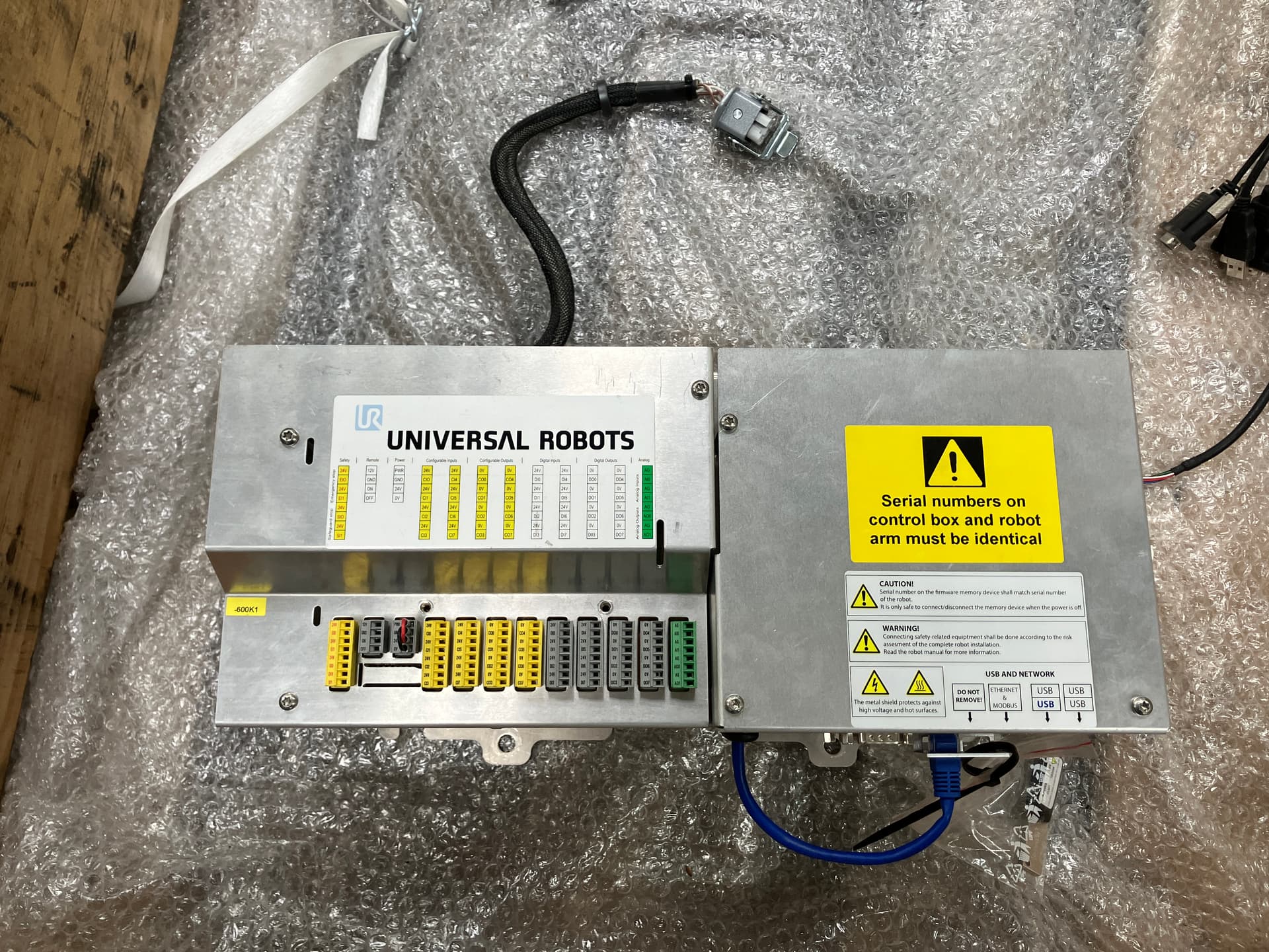
our company has purchased a used UR10 from a machine dealer. My colleagues and I are supposed to set up a test track. But first, we need to make the robot operational.
Our problems are as follows:
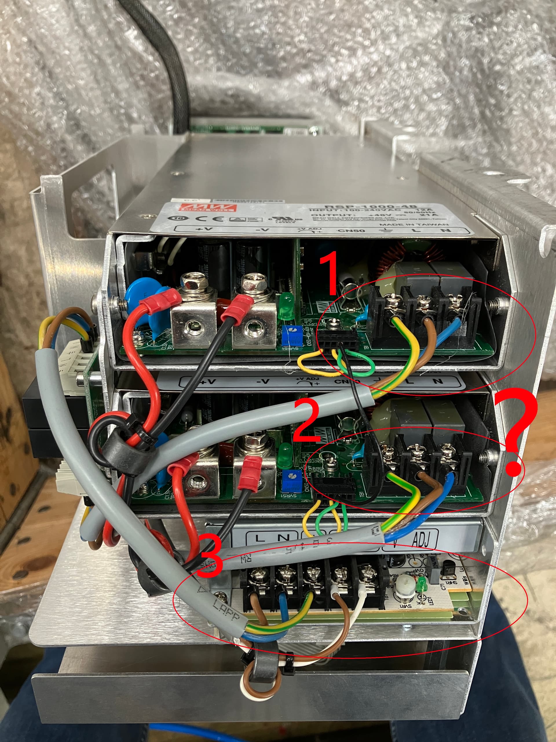
1. Unfortunately, the robot only comes with the controller. A control cabinet is missing. The power supply that leads to the controller is also missing. There should be a power line with a socket/IEC connector. Our electrician is willing to create something himself, but he is unsure where exactly to connect the wires. Perhaps you could provide some advice. I have taken photos to illustrate the situation better.
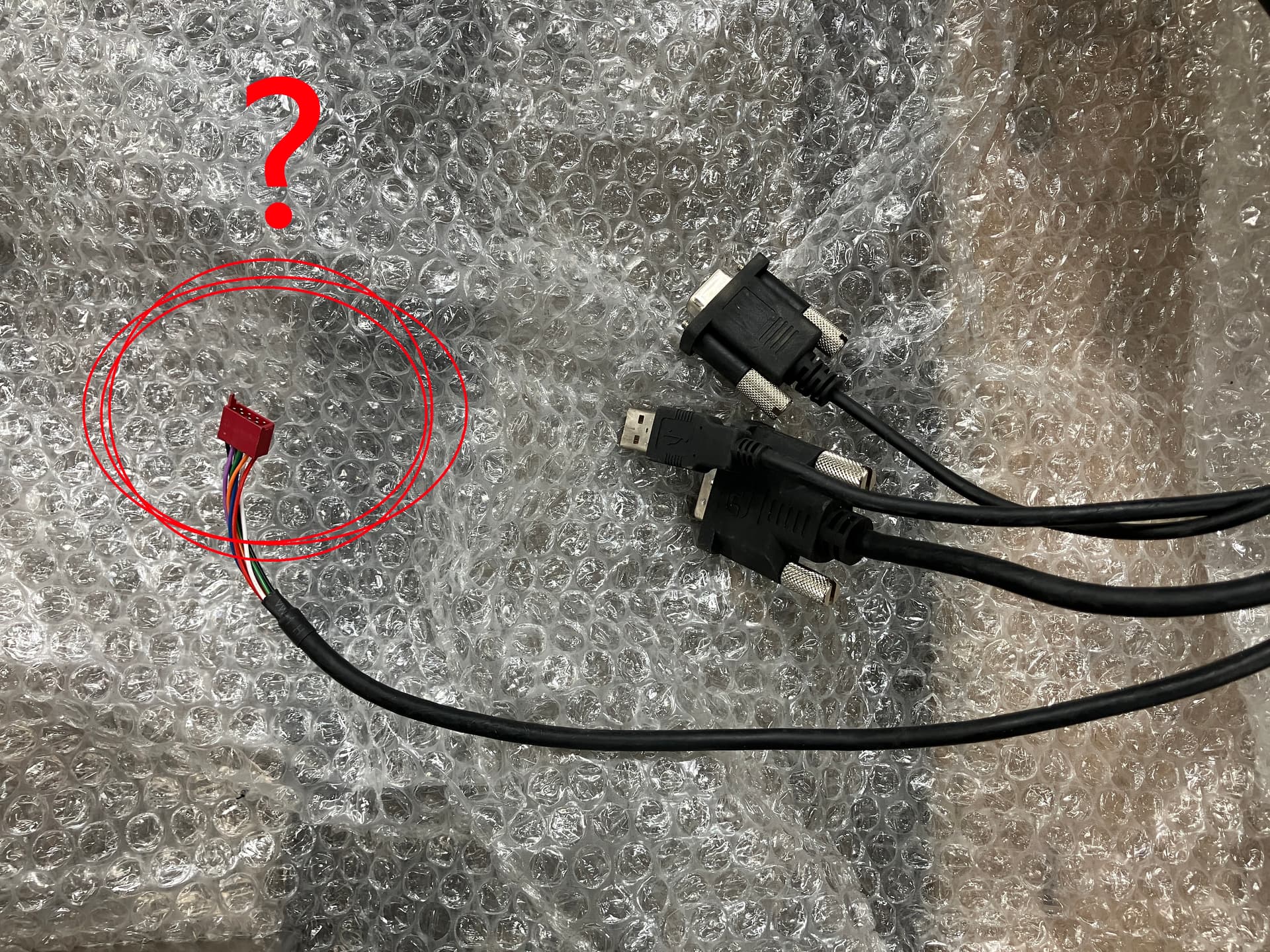
2. There is a red connector on the cable of the panel - see the picture. Where does this plug in?
---
### Author:  [@efn](https://forum.universal-robots.com/u/efn)
#### Post date: [March 24, 2025, 7:44am UTC](https://forum.universal-robots.com/t/electrical-connection-of-the-controller-how-to/39220/2 "2025-03-24T07:44:58Z")
Here’s the electrical diagram for the controller. It’s really fairly simple - just connect your supply to the Current Distributor (small PCB to the left of the PSUs on your 2nd image).

The red connector connects to RS485/12V on the Safety Control Board.
---
### Author:  [@robert.huels](https://forum.universal-robots.com/u/robert.huels)
#### Post date: [March 31, 2025, 5:00am UTC](https://forum.universal-robots.com/t/electrical-connection-of-the-controller-how-to/39220/3 "2025-03-31T05:00:51Z")
Thank you very much for the hints.